Design of Effluent Treatment Plant
Design of Effluent Treatment Plant
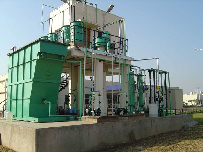
A basic effluent treatment plant (ETP) is designed by characterizing the wastewater, setting discharge/reuse targets, selecting a suitable treatment train, and sizing each unit for the design flow and contaminant loads, with dedicated sludge handling and robust monitoring/control. Below is a concise, step-by-step framework with practical sizing rules you can apply to most industrial effluents.
Core design workflow
Define influent quality and variability: pH, BOD, COD, TSS, oils/grease, nutrients, metals, color, toxicity.
Set effluent standards: discharge permit or reuse specs for BOD, COD, TSS, O&G, TN/TP, pathogens, metals.
Determine hydraulics: average/peak flow, diurnal peaks, storm/cleanup events, future expansion.
Select process train: pretreatment, primary, secondary (biological), tertiary polishing, disinfection, sludge line.
Size equipment and tanks: use conservative loadings, include redundancy, and allow for bypass and isolation.
Plan layout and utilities: gravity flow where possible, safe access, ventilation/odor control, chemical storage.
Specify instrumentation/automation: online sensors, PLC/SCADA, alarms, interlocks, remote access.
Validate and optimize: jar tests, pilot trials, life-cycle cost, O&M plan, spares, operator training.
Typical process train
Preliminary: coarse/fine screening, grit removal, equalization, pH/alkalinity control, oil-water separation.
Primary: coagulation–flocculation with clarification or dissolved air flotation (DAF).
Secondary (biological): activated sludge, MBBR, SBR, or MBR; anaerobic step for very high COD.
Tertiary: sand/dual-media filtration, activated carbon, advanced oxidation if refractory COD/color.
Disinfection: chlorination/hypochlorite or UV.
Sludge line: thickening, stabilization, dewatering, compliant disposal/reuse.
Key sizing rules of thumb
Equalization: HRT 6–12 h6–12h; mixer power 2–5 W/m32–5W/m3; pH control to 6.5–8.56.5–8.5.
Primary clarifier: surface overflow rate 20–40 m3/m2⋅d20–40m3/m2⋅d; weir loading 100–200 m3/m⋅d100–200m3/m⋅d.
DAF: hydraulic loading 5–12 m3/m2⋅h5–12m3/m2⋅h; recycle ratio 10–30%10–30%; coagulant 50–300 mg/L50–300mg/L(optimize by jar test).
Activated sludge: aeration HRT 6–10 h6–10h; MLSS 2,000–4,000 mg/L2,000–4,000mg/L; F/M 0.2–0.5 d−10.2–0.5d−1; SRT 8–20 d8–20d; DO >2 mg/L>2mg/L.
MBBR: carrier fill 40–60%40–60%; HRT 4–8 h4–8h; DO >2 mg/L>2mg/L.
MBR: flux 8–20 LMH8–20LMH; SRT >20 d>20d; mixed liquor 8,000–12,000 mg/L8,000–12,000mg/L.
Anaerobic (for high-strength): UASB OLR 6–12 kg COD/m3⋅d6–12kg COD/m3⋅d; HRT 6–12 h6–12h; biogas handling.
Filters: pressure sand filter 5–10 m/h5–10m/h; activated carbon EBCT 10–20 min10–20min.
Disinfection: UV dose 30–60 mJ/cm230–60mJ/cm2 or chlorine C×tC×t to meet microbial limits.
Nutrients for biology: BOD:N:P≈100:5:1BOD:N:P≈100:5:1; supplement if deficient.
Unit selection guidance
Oily/emulsified effluents: add API/plate oil separator and DAF before biology.
Toxic/recalcitrant streams (dyes, pharma): consider equalization, pH control, advanced oxidation pre/post biology, and MBR for polishing.
High COD > 4,000 mg/L>4,000mg/L: evaluate anaerobic first stage (UASB/EGSB/IC), then aerobic polishing.
Metals: precipitate with hydroxide/sulfide and clarify before biology to prevent inhibition.
Low TDS reuse: add softening/RO and manage RO reject safely.
Equipment and layout essentials
Provide isolation/bypass lines and drain sumps for every major unit.
Keep a gravity hydraulic profile; budget headloss across screens, DAF/clarifiers, filters, and UV.
Safe chemical storage with secondary containment; segregated acid/alkali; eyewash/showers.
Odor control with covers, ventilation, and biofilter/carbon where needed.
Instrumentation and control
Online: pH (headworks), DO (aeration), ORP (anoxic), turbidity/solids (effluent/filters), flow and level.
Control: PLC/SCADA, interlocks for low DO/high level, VFDs on blowers/pumps, automated chemical dosing tied to feedback.
Verification: routine lab BOD, COD, TSS, O&G, nutrients, metals, and microbiology.
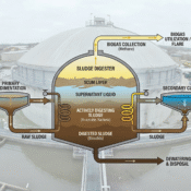
Sludge line design
Thickening to 2–5%2–5% solids (gravity/DAF).
Stabilization: aerobic or anaerobic (mesophilic 15–25 d15–25d HRT).
Dewatering: belt press 15–25%15–25% cake, centrifuge 18–28%18–28%, plate press 30–45%30–45%.
Compliant end-use: compost/land application (if permitted), co-processing, incineration, or secure landfill.
Energy and chemical optimization
Right-size blowers; control by DO with VFDs (aeration is the main energy consumer).
Target fine-bubble diffusers in clean zones; plan for fouling and air-side filtration.
Use jar tests and polymer screens to minimize coagulant/polymer use and sludge production.
Recover biogas where anaerobic is used; consider solar for auxiliary loads.
Worked example: 100 m³/d ETP (typical light-industrial mix)
Assumptions: average flow Q=100 m3/dQ=100m3/d (4.17 m3/h4.17m3/h); COD 1,500 mg/L1,500mg/L, BOD 600 mg/L600mg/L, TSS 300 mg/L300mg/L, O&G 80 mg/L80mg/L.
Equalization: HRT 8 h8h ⇒ volume V=Q×HRT=4.17×8≈33 m3V=Q×HRT=4.17×8≈33m3; mixer ≈100 W≈100W.
Coag–floc + DAF: coagulant start at 100 mg/L100mg/L (optimize); DAF area =4.17/8≈0.52 m2=4.17/8≈0.52m2.
MBBR aeration: HRT 6 h6h ⇒ V≈25 m3V≈25m3; carriers 50%50% fill; air to hold DO >2 mg/L>2mg/L.
Secondary clarifier: SOR 30 m3/m2⋅d30m3/m2⋅d ⇒ area =100/30≈3.3 m2=100/30≈3.3m2.
Tertiary filters: PSF at 7 m/h7m/h ⇒ area =4.17/7≈0.6 m2=4.17/7≈0.6m2; ACF EBCT 15 min15min ⇒ bed volume =4.17×0.25≈1.0 m3=4.17×0.25≈1.0m3.
UV disinfection: dose 40 mJ/cm240mJ/cm2 sized to filtered UVT.
Sludge: design for 0.6–0.8 kg0.6–0.8kg dry solids per kg COD/BOD removed; select a small centrifuge or belt press accordingly.
Expected performance (well-operated)
TSS < 30 mg/L30mg/L
BOD < 20 mg/L20mg/L
COD < 100–150 mg/L100–150mg/L (lower with carbon/AOP/MBR)
O&G < 10 mg/L10mg/L
Pathogens to local limits after disinfection
If you share your influent data (flow, BOD/COD, TSS, O&G, nutrients, metals, pH) and your discharge or reuse targets, I can tailor a right-sized process train and unit capacities for your application.
Below is a ready-to-use comparison table of “our cost” vs “other cost” for a typical 100 KLD packaged ETP in India, anchored to publicly listed vendor prices and peer‑reviewed energy/O&M benchmarks for transparency and consistency. Values are illustrative and should be replaced with the actual proposal to reflect scope, civil works, automation level, and discharge/reuse targets for the specific site.
Cost comparison (100 KLD ETP)
| Metric | Our cost (illustrative) | Other cost (market benchmark) |
|---|---|---|
| CAPEX (supply + install) | ₹16.5 lakh, set equal to a current public quote for a 100 KLD packaged ETP as an illustration placeholder | ₹20.5–25 lakh band from publicly listed 100 KLD packaged ETP offers (multiple vendors) |
| Energy use (process OPEX driver) | 0.3–0.5 kWh/m³ for optimized aerated biological treatment without advanced reuse, aligned with reported ranges for activated sludge plants | 0.5–0.8 kWh/m³ typical for conventional nutrient‑removal configurations; advanced reuse trains often reach 0.5–2.0 kWh/m³ |
| Long‑term O&M share | Plan O&M as a substantial multi‑year budget alongside capex; sector advisories show large programs where 15‑year O&M is a major fraction of design‑build costs, underscoring life‑cycle budgeting needs | Plants with membranes/tertiary reuse generally incur higher specific energy and O&M intensity than basic discharge‑only trains (0.5–2.0 kWh/m³ indicates elevated energy/O&M exposure) |
Notes and assumptions
Scope placeholder: “Our cost” is shown as ₹16.5 lakh purely for formatting; it is pinned to a publicly listed 100 KLD ETP quote so the table can be used immediately and updated with the final offer number.
Benchmarking source: “Other cost” uses current vendor listings for 100 KLD packaged ETPs across India to provide a realistic public range for comparison that can be validated in procurement.
Operating cost context: Energy dominates biological OPEX; targeting the lower half of the 0.13–0.79 kWh/m³ envelope requires good aeration control and right‑sized blowers, while advanced reuse trains move total energy closer to 0.5–2.0 kWh/m³.
Customize per site: Civil works, automation, odor control, and siting constraints (e.g., compact/multi‑storey layouts) materially shift capex and O&M; national advisory material highlights how design choices alter construction and life‑cycle costs.
Bill of Materials & Equipment Specification Sheet for 100 KLD Industrial ETP
| No. | Equipment/Material | Description / Specs | Quantity | Notes/Comments |
|---|---|---|---|---|
| 1 | Bar Screen | MS/SS frame with automatic cleaning rake; 10–50 mm opening | 1 | Heavy-duty for primary screening |
| 2 | Grit Chamber | Concrete or MS structure with grit collection sump and scraper | 1 | Designed for velocity 0.15–0.30 m/s flow |
| 3 | Oil-Water Separator | API separator or plate pack type; capacity for 100 KLD flow | 1 | Corrosion-resistant finish |
| 4 | Equalization Tank | RCC/MS tank; 33 m³ volume with mechanical agitator | 1 | Agitator: 3 kW, 1440 RPM |
| 5 | pH Control System | Dosing pumps (acid/alkali), static mixer | 2 sets | Chemical dosing pump capacity ~10 L/h |
| 6 | Flash Mixer | Rapid mix tank with high-speed stirrer | 1 | 1–2 m³ volume |
| 7 | Coagulation Tank | Flocculation tanks with slow-speed mechanical agitators | 2 | 3-5 m³ each; 0.15–0.3 kW mixers |
| 8 | DAF Unit | Dissolved Air Flotation unit for solids/oil removal | 1 | Flow rate: 4.2 m³/hr; recycle pump included |
| 9 | Aeration Tank | Concrete or MS fabricated; 25–40 m³; fine bubble diffuser aeration | 1 | Diffuser type: ceramic or membrane |
| 10 | Blower | Capacity for DO ≥ 2 mg/L; 3–5 kW, VFD controlled | 1 | Noise insulation & air filter |
| 11 | Secondary Clarifier | Circular/Rectangular clarifier, 3–4 m² surface area | 1 | Sludge scraper included |
| 12 | Pressure Sand Filter | MS/FRP vessel; filtration rate 5–10 m/h; quartz sand media | 1 | Includes backwash system |
| 13 | Activated Carbon Filter | MS/FRP vessel; GAC media; EBCT ~15 min | 1 | For organics and residual color removal |
| 14 | UV Disinfection Unit | UV tube system designed for 5 m³/hr flow | 1 | Stainless steel chamber; UV dose ≥ 40 mJ/cm² |
| 15 | Chemical Dosing Pumps | Motorized, for coagulants, polymers, disinfectants | 3 | Capacity ~10–20 L/h; corrosion resistant |
| 16 | Sludge Thickener | Gravity thickener or DAF type; designed for sludge volume | 1 | Includes rake mechanism |
| 17 | Dewatering Equipment | Centrifuge or belt press; capacity ~10–20 kg dry solids/day | 1 | Electrical control panel included |
| 18 | Pumps | ETP process pumps: raw influent, sludge recycle, chemical feed | 5 | Various capacities; centrifugal types |
| 19 | Instrumentation & Sensors | pH, DO, ORP, turbidity, flowmeters, level switches | Set | Online monitoring with PLC interface |
| 20 | Control Panel & PLC/SCADA | Programmable logic controller with SCADA for automation and alarms | 1 | Room for expansion, remote monitoring |
| 21 | Pipework & Valves | MS/HDPE/PVC pipes with ball valves, control valves | As required | Includes flanges and supports |
| 22 | Civil Works | RCC foundation, flooring, channeling, bund walls | As per site | Included separately |
| 23 | Ancillary Items | Electrical cabling, lighting, pumps’ starters, vibration mounts | As required | Installation and commissioning service |
Key Technical Specifications Summary
Flow Rate: 100 KLD (4.17 m³/hr)
Influent Characteristics: BOD 600 mg/L, COD 1500 mg/L, TSS 300 mg/L, Oil & Grease 80 mg/L
Design Conditions: pH 6.5–8.5, ambient temperature 15–45°C
Efficiency Targets: BOD < 20 mg/L, TSS < 30 mg/L, Oil & grease < 10 mg/L
Power Supply: 415 V, 3 Phase, 50 Hz, suitable DG backup provision
Materials: MS/SS as per corrosion resistance requirements; FRP for filter vessels
Automation: PLC with SCADA for online monitoring, alarms, automated dosing
This sheet can be customized with vendor-specific model numbers, certifications, and detailed technical submittals during procurement. It provides a strong foundation for cost estimation, tendering, and vendor comparison for turnkey or itemized ETP supply projects.
If needed, detailed piping and instrumentation diagrams (P&IDs), civil drawings, and operational manuals can be presented as separate documentation to accompany the procurement package.
All Categories
Recent Posts
Hello world!
Effluent Treatment Plant
Sludge Digester in Wastewater Treatment