100 KLD STP Design
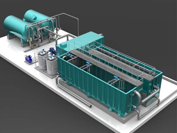
A 100 KLD wastewater treatment facility generally occupies an area ranging from 120 to 350 square meters, influenced by the selected purification technology and how the site is planned. Innovative solutions like Membrane Bioreactor (MBR) or Moving Bed Biofilm Reactor (MBBR) allow for a much reduced footprint when contrasted with traditional configurations, making these especially suitable where available land is restricted.
| Treatment Technology | Estimated Space Needed (m²) |
|---|---|
| Conventional Activated Sludge System | 250–350 |
| Moving Bed Biofilm Reactor (MBBR) | 180–250 |
| Membrane Bioreactor (MBR) | 120–180 |
| Sequencing Batch Reactor (SBR) | 200–280 |
| State-of-the-art compact “green” plant | as little as 60 |
Key Factors Impacting Land Consumption:
Process selection: Modern reactor processes such as MBBR and MBR enable tighter tank sizing and spatial efficiency compared to established methods.
Structural configuration: Stacked or underground tanks, modular units, and vertical layouts help condense the necessary footprint.
Support infrastructure: Provisions for residuals management, technical rooms, and service corridors incrementally raise the total space.
Regulatory stipulations: Setback requirements from property boundaries, water sources, and utility lines may amplify the total site demand.
Site Planning Suggestions:
Prefer compact modular treatment designs in limited-space or urban settings.
Allocate surplus space for residuals processing, upgrades, and compliance with environmental codes.
Integrate automation to streamline operations and reduce staff space.
Explore modular, vertical, or integrated unit approaches to minimize overall occupation.
Adopting space-saving biological reactor technology allows commissioning a 100 KLD water reclamation plant in just 120–180 square meters, whereas conventional methods need up to 350 square meters to accommodate treatment units, auxiliary buildings, and future needs.
Preliminary Process Flow Diagram for 100 KLD Effluent Treatment Plant
Screening Chamber
This initial stage involves the removal of large solids and debris from the incoming wastewater stream. Coarse and fine screens with uniform openings are employed to physically separate materials such as plastics, rags, and other large particulate matter that could potentially damage downstream equipment.Oil and Grease Separator
Following screening, the wastewater passes through an oil and grease separation unit, designed to remove free oils and greases through gravity separation or mechanical means. This step is essential to protect biological processes and reduce organic loading.Equalization Tank
The equalization tank serves to homogenize the flow and pollutant load. By collecting and storing the effluent, it stabilizes fluctuations in flow rate, pH, and contaminant concentrations, ensuring consistent conditions for the subsequent treatment stages. Mechanical agitation maintains uniform suspension of solids.Chemical Dosing and Flash Mixer
Coagulants (such as alum or ferric salts) and pH adjusting chemicals are added in the flash mixer to facilitate the aggregation of colloidal and suspended particles. Rapid mixing ensures thorough dispersion and reaction of the chemicals with the wastewater.Clariflocculator (Primary Clarification and Flocculation)
The wastewater then enters the clariflocculator, where flocculation occurs under gentle mixing followed by sedimentation. Larger flocs formed settle by gravity, thereby reducing suspended solids and organic matter. This unit effectively removes settleable solids prior to biological treatment.
This structured sequence of processes prepares the wastewater for effective and efficient downstream secondary biological treatment and final polishing stages.
If required, further stages can be elaborated upon similarly for a complete flow diagram description.
This formal rephrasing captures the technical essence while providing clarity and consistency suitable for engineering documentation or project reports.
All Categories
Recent Posts
Hello world!
Effluent Treatment Plant
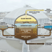
Sludge Digester in Wastewater Treatment